Skip to content
in cooperation withCIC Berlin

01 / 3D PRINTING

From a digital model.To a physical part.

Choose by part, material and surface. Each project path shows what to prepare and how to check the result.

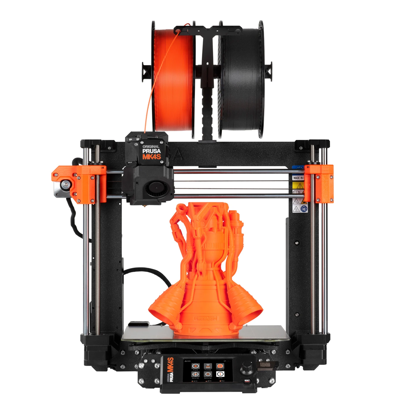
Prusa MK4S
PRODUCT VIEW · MAKR-0001–0004ENLARGE ↗

01 / MAKR-0001–0004

Prusa MK4S

4 printers · 250 × 210 × 220 mm

Use requires the relevant induction and booking.

Equipment & project paths 2

A practical starting point for enclosures, brackets and fit tests. Four printers also let you compare several design variants.

Enclosures & bracketsFit testsSmall batches

Equipment at the Lab

Four MK4S printers. Match the nozzle and build sheet on the individual machine.

Prepare for your project

PrusaSlicer, suitable spool and plate. A 0.4 mm nozzle is a useful starting point for small features; 0.6 mm can build larger sections faster. Installed nozzle and profile must match.

PROJECT PATH 01

An enclosure that fits

  1. Dimension connectors and screw holes in CAD; export a critical section first.
  2. Slice and print the section with the correct MK4S and nozzle profile.
  3. Test against the actual component, adjust clearance, then print the full enclosure.

Your resultAn enclosure with verified connector and mounting clearances.

If the test binds, correct the CAD dimensions first.

PROJECT PATH 02

Compare three versions

  1. Change one feature, such as wall thickness or grip shape; name each version.
  2. Use the same material and comparable profiles; record machines and orientation.
  3. Apply the same test to every version and save the best file.

Your resultA design choice supported by a repeatable comparison.

If print defects differ, establish comparable print quality first.

Open frame: material and ambient conditions must be compatible.

Prusa CORE One L
PRODUCT VIEW · MAKR-0009–0010ENLARGE ↗

02 / MAKR-0009–0010

Prusa CORE One L

2 printers · 300 × 300 × 330 mm

Use requires the relevant induction and booking.

Equipment & project paths 2

For larger functional parts and materials that need a controlled, enclosed build space.

Large enclosuresFixturesMaterial-specific prototypes

Equipment at the Lab

Two CORE One L printers with enclosed build chambers.

Prepare for your project

Correct PrusaSlicer profile, a compatible build sheet and prepared spool. Abrasive filament requires a suitable nozzle.

PROJECT PATH 01

Print a large part in one piece

  1. Orient the model and check space for brim, supports and tool movements.
  2. Test a critical corner or joint as a small section.
  3. Print the full part, allow it to cool, then compare flatness and key dimensions.

Your resultA large part with checked dimensions.

If corners lift, stop the print and review the cause with the team.

PROJECT PATH 02

Develop an assembly jig

  1. Define contact faces, loads and operating temperature.
  2. Choose material with the team and print a small functional test.
  3. Print the jig and check fit and access on the powered-off assembly.

Your resultA reusable jig for a defined task.

Do not use unverified parts for safety-critical loads.

An enclosure does not make every material suitable. Material approval and the correct profile still apply.

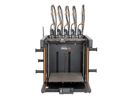
Prusa XL · 5 toolheads
PRODUCT VIEW · MAKR-0008ENLARGE ↗

03 / MAKR-0008

Prusa XL · 5 toolheads

360 × 360 × 360 mm · 5 toolheads

Use requires the relevant induction and booking.

Equipment & project paths 2

Large builds and separate tools for multicolour models or compatible model and support materials.

Large modelsMulticolour letteringSeparate support materials

Equipment at the Lab

XL with five toolheads. The installed nozzles determine the profile.

Prepare for your project

PrusaSlicer, compatible filaments and a clear mapping from spool to tool.

PROJECT PATH 01

Print lettering into the part

  1. Create the body and lettering as separate volumes.
  2. Assign volumes to tools and inspect the layer preview.
  3. Print a lettering sample, then produce the complete sign or control element.

Your resultIntegrated lettering without an adhesive label.

Widen lettering in CAD if features are too narrow.

PROJECT PATH 02

Separate supports deliberately

  1. Identify surfaces needing supports and plan access for removal.
  2. Choose a compatible material pair and tool profile with the team.
  3. Test a small overhang and check removal before starting the full part.

Your resultA complex part with manageable finishing.

Use soluble supports only with an appropriate washing and disposal process.

Multiple tools do not guarantee adhesion between different plastics.

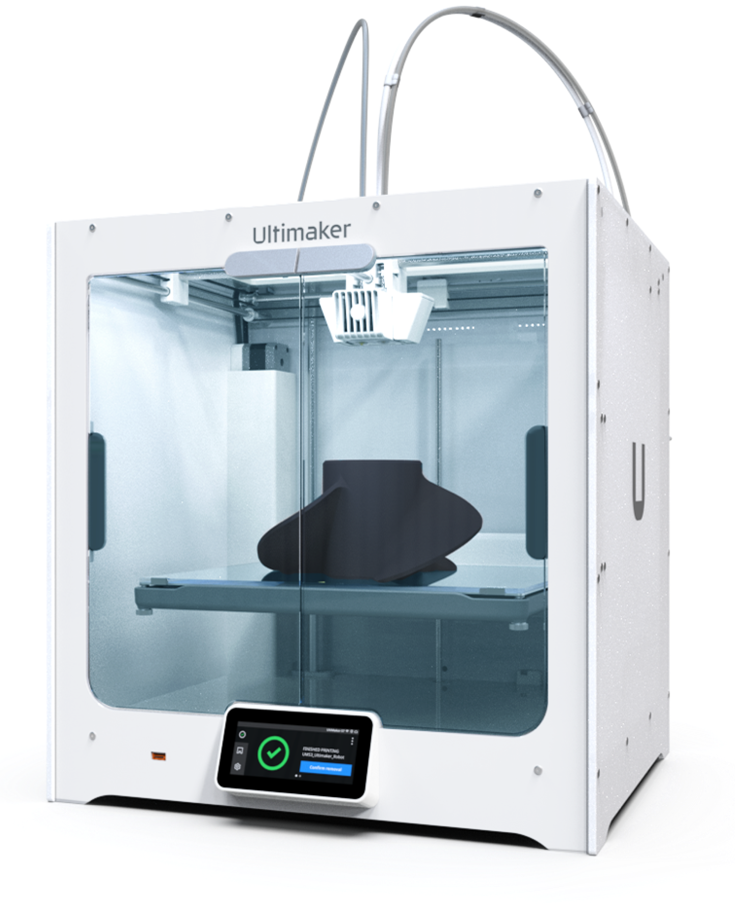
Ultimaker S5
PRODUCT VIEW · MAKR-0005ENLARGE ↗

04 / MAKR-0005

Ultimaker S5

330 × 240 × 300 mm · dual extrusion

Use requires the relevant induction and booking.

Equipment & project paths 2

Two extruders for functional models and supported geometries, especially when a clean underside matters.

Functional modelsComplex overhangsTwo-colour parts

Equipment at the Lab

S5 with two Print Core positions.

Prepare for your project

UltiMaker Cura, suitable Print Cores and approved filaments. PVA needs the correct core, dry material and an agreed finishing process.

PROJECT PATH 01

A part with a clean underside

  1. Orient the part in Cura and select support areas deliberately.
  2. Match materials, cores and support strategy; test a short overhang.
  3. Print, remove supports using the appropriate method and inspect functional surfaces.

Your resultA functional model with accessible, clean contours.

Resolve damp or incompatible support material before printing.

PROJECT PATH 02

Two colours with a purpose

  1. Model a warning area, scale or grip zone as a separate volume.
  2. Assign compatible materials to both volumes and check the preview for gaps.
  3. Print a sample and test legibility and bonding.

Your resultA model whose colour communicates function.

Change the material pairing if bonding is poor.

Match core type and material; not every filament suits every core.

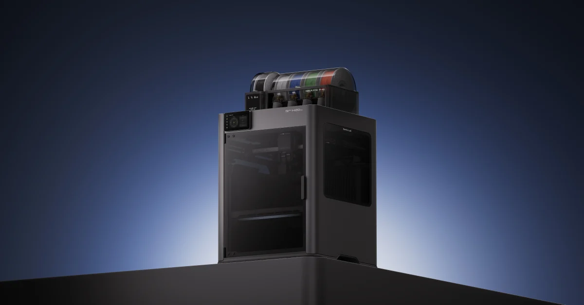
Bambu Lab H2D Pro
PRODUCT VIEW · MAKR-0013ENLARGE ↗

05 / MAKR-0013

Bambu Lab H2D Pro

Dual nozzle · enclosed build chamber

Being set up · use after approval by the Maker team.

Equipment & project paths 2

For demanding functional prototypes using two nozzles: assign model and supports to different tools.

Functional prototypesModel + support materialTwo materials

Equipment at the Lab

H2D Pro with two nozzles.

Prepare for your project

Bambu Studio, approved filament, suitable plate and nozzles. Confirm AMS and drying accessories with the team when planning.

PROJECT PATH 01

A functional assembly prototype

  1. Record expected loads, temperature and installation position.
  2. Choose material and orientation; print a joint as a test.
  3. Produce the complete part and carry out the defined functional test.

Your resultA tested sample to inform the next design decision.

A successful sample is not a qualified production component.

PROJECT PATH 02

Split model and supports

  1. Identify critical overhangs and access for support removal.
  2. Assign nozzles and materials correctly in Bambu Studio.
  3. Test the contact interface, then print the complete part with the same combination.

Your resultA complex part with a planned support-removal process.

If supports cannot be removed, change geometry or strategy.

Check temperature requirements and material compatibility for both tools together.

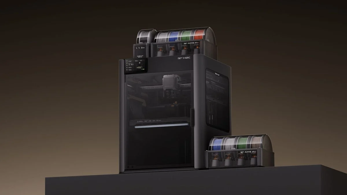
Bambu Lab H2C · Vortek
PRODUCT VIEW · MAKR-0014ENLARGE ↗

06 / MAKR-0014

Bambu Lab H2C · Vortek

Vortek · automatic hotend changing

Being set up · use after approval by the Maker team.

Equipment & project paths 2

For colour-coded models and multi-material projects. Tool changes support separate tasks within a print.

Multicolour modelsControl elementsMaterial combinations

Equipment at the Lab

H2C with Vortek: up to six interchangeable hotends and an additional nozzle. Check the hotends and filament paths actually available at the machine.

Prepare for your project

Bambu Studio and a material/tool plan. Confirm available hotends, filament feeds and material pairings with the team.

PROJECT PATH 01

A model that explains itself

  1. Separate functional parts in CAD and assign meaningful colours.
  2. Assign volumes to available tools; inspect changes and material estimates.
  3. Test a section, print the full model and include a colour key.

Your resultA clear demonstration model for presentations.

Reduce excessive changes by grouping colour regions sensibly.

PROJECT PATH 02

Test rigid and flexible regions

  1. Design a small joint sample; consider mechanical interlocking.
  2. Have the material pairing and feed path checked for suitability.
  3. Print the sample and compare flex and bonding before scaling up.

Your resultA verified material combination or a justified alternative.

Do not plan flexible filament without a suitable, approved feed path.

The usable number of materials depends on the installed setup.

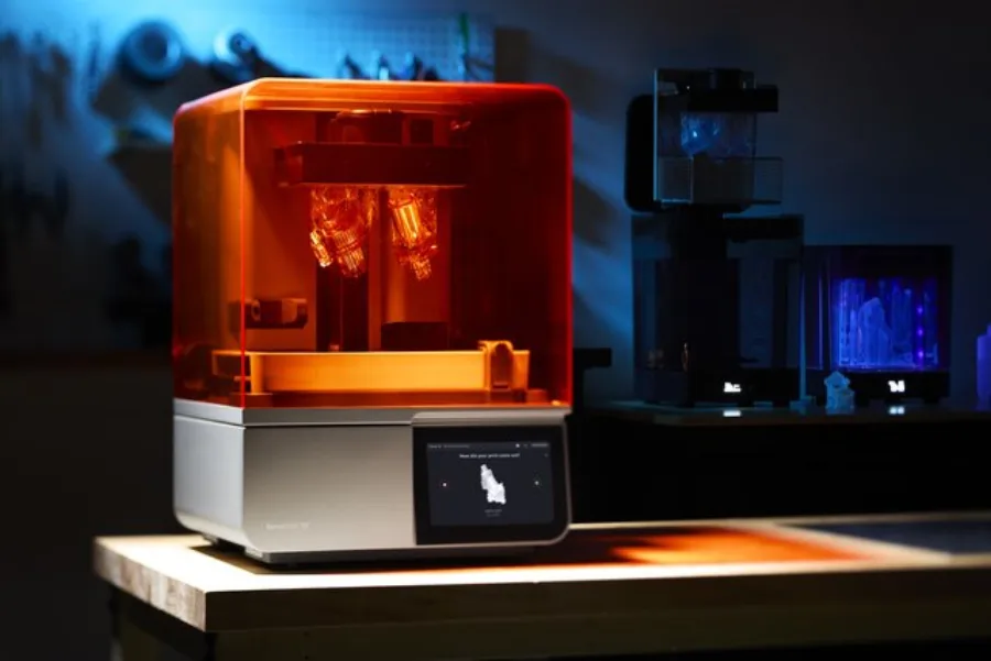
Formlabs Form 4
PRODUCT VIEW · MAKR-0006ENLARGE ↗

07 / MAKR-0006

Formlabs Form 4

Resin · fine detail and surface quality

Supervised use · arrange an appointment with the Maker team.

Equipment & project paths 2

For small features, detailed display models and smooth surfaces. Washing, drying and post-curing are part of producing the finished part.

Design samplesFine featuresFit and form studies

Equipment at the Lab

Form 4. Resin, tank and build platform must suit the application.

Prepare for your project

PreForm, suitable resin and the supervised washing, drying and curing setup. Arrange protection and disposal beforehand.

PROJECT PATH 01

A detailed design sample

  1. Identify visible surfaces and details; review orientation and supports in PreForm.
  2. Print with the selected resin and wash under supervision.
  3. Dry fully, post-cure according to material instructions and inspect the surface.

Your resultA finished sample for evaluating form and surface quality.

Do not use tacky or incompletely cured parts.

PROJECT PATH 02

Compare small features

  1. Model a test strip with several text sizes, grooves or holes.
  2. Produce samples with the same orientation and post-processing.
  3. Measure or photograph features and carry usable dimensions back into CAD.

Your resultA practical feature-size guide for the selected resin and process.

Holes and gaps can trap resin; check that they can be cleaned.

Use only fully post-processed parts. A resin name does not establish skin-contact, food or medical approval.

Cookie Consent Banner by Real Cookie Banner